Instant Connection for Pixel Streaming
— New Feature Automated Setup

How to Run SOLIDWORKS on Googlebook: Complete CAD Guide
Architecture
-
How to Run SOLIDWORKS on Googlebook: Complete CAD Guide
Architecture
How to Run SOLIDWORKS on Googlebook: Complete CAD Guide
Architecture
-
Table of Contents
Designing a mechanical part involves more than getting its shape right. Hole positions need to remain consistent when dimensions change, components need to fit together, and drawings need to reflect the latest model. If you use a Googlebook, the challenge is finding a workspace where you can carry out that entire process with desktop SOLIDWORKS.
The Windows application does not install natively on Googlebook. However, you can access it through a remote Windows computer that handles the modeling, assembly calculations, and graphics processing while your Googlebook displays the workspace and sends your keyboard and mouse input.
Vagon Cloud Computer provides that approach: a Windows workspace where you can install SOLIDWORKS, configure your design tools, and develop projects from initial sketches through manufacturing deliverables. Your Googlebook becomes the access point rather than the machine responsible for running the CAD software.
You still need a valid SOLIDWORKS license and a Windows configuration that meets your chosen release’s system requirements. With those foundations in place and a stable internet connection, you can build new parts, manage assemblies, prepare drawings, and organize the files your next design depends on.

Source: SOLIDWORKS Blog
Desktop SOLIDWORKS, Cloud Services, or xDesign?
Before setting up your workspace, distinguish between accessing desktop SOLIDWORKS through a browser and using a CAD application built to run in one. Both can involve cloud services, but they provide different working environments.
Option | What you are using | Where the CAD application runs |
|---|---|---|
Desktop SOLIDWORKS | Installed software for parts, assemblies, and drawings | A Windows computer |
Desktop SOLIDWORKS with Cloud Services | Installed CAD software with connected sharing and data-management services | A Windows computer |
SOLIDWORKS xDesign | A separate browser-native CAD application | A cloud-based environment accessed through a browser |
Desktop SOLIDWORKS on Vagon | The installed Windows application accessed remotely | Your Vagon cloud computer |
The phrase “with Cloud Services” does not mean desktop SOLIDWORKS becomes a browser-native application. Depending on your SOLIDWORKS license, installation and sign-in methods differ, but the desktop software still needs a compatible Windows environment.
SOLIDWORKS xDesign takes a different approach. It provides browser-based design tools and deserves consideration if that workflow suits your needs. However, you should not assume it reproduces every desktop feature, add-in, or native-file editing workflow.

Source: SOLIDWORKS Blog
For users who need the desktop FeatureManager, existing SOLIDWORKS templates, native parts and assemblies, or specific Windows-based tools, a remote workstation is the relevant route. With Vagon, the browser provides access to that workstation. SOLIDWORKS itself runs inside Windows, rather than being installed on your Googlebook or replaced by a browser-based viewer.
Set Up Your SOLIDWORKS Workspace on Vagon
The setup brings together three things: your cloud computer, your SOLIDWORKS installation, and the files and settings you use for design. Configure these once, then use the workspace for new projects and ongoing work.
1. Create Your Cloud Computer
Create a Vagon Cloud Computer and choose an available region near your location to help reduce connection latency. Select resources appropriate for your work, allowing more memory for complex assemblies and other applications running alongside SOLIDWORKS.
Open the Windows workspace through your Googlebook’s browser. Before installing software, check the actual Windows edition and version against the requirements for your chosen SOLIDWORKS release. A remote Windows computer is not automatically a supported configuration for every release.
2. Confirm Your License and Installation Method
Use your own valid SOLIDWORKS entitlement. Vagon provides the computer, not a SOLIDWORKS subscription.
Your license type determines how you install and authorize the application. A named-user installation, machine-locked license, and SolidNetWork license can require different steps. For a company-managed license, confirm the cloud deployment with your administrator or reseller, including any required connection to a license server.
3. Install SOLIDWORKS From Your Approved Source
SOLIDWORKS is not currently listed in Vagon’s preinstalled application library. Install it inside the Windows workspace using your official download, platform-based installation method, or company deployment package.
Choose the release and service pack required by your projects and collaborators. Add only the products you need, such as Toolbox or licensed analysis tools. If your organization uses PDM, coordinate the client installation and vault access with IT.
After installation, launch SOLIDWORKS and confirm that licensing works before transferring a complete project library.
4. Bring In Files and Configure Your Workspace
Use Vagon Files to transfer existing project packages, reference documents, and custom resources. Place active CAD projects in an organized folder on the cloud computer’s Windows disk, keeping assembly references together.
For new work, configure your part, assembly, and drawing templates, document units, material libraries, and file locations. Then create a simple part, save it, close it, and reopen it. This confirms that the basic workspace is ready before you build a more involved design.
Build Parametric Parts That Survive Design Changes
Once SOLIDWORKS is running, start with a part whose dimensions you can deliberately change. A mounting bracket is a useful example: its thickness, mounting-hole spacing, and overall height should remain editable without forcing you to rebuild the geometry manually.
The modeling tools work inside your Windows workspace. Your Googlebook provides access to the sketch, FeatureManager tree, and graphics area.
Establish the Design Intent in Your Sketch
Create a new part using the appropriate template and confirm its units. Choose a reference plane that makes sense for the bracket’s orientation, then position the initial profile relative to the origin.
Use sketch relations to describe how geometry should behave. Horizontal, vertical, coincident, and symmetric relations preserve relationships; dimensions control the values that need to change.

Source: SOLIDWORKS Blog
For example, centering two mounting holes around a construction line communicates a different intention from positioning each hole independently from an arbitrary edge.
A fully defined sketch has its geometry constrained by dimensions and relations. That is a useful checkpoint, but the constraints should reflect the intended design. Fixing every entity in place may remove movement without creating a practical parametric model.
Build Features in a Clear Sequence
Turn the profile into a solid with Extruded Boss/Base, then add the remaining features according to how the bracket should be constructed.
A straightforward feature sequence could include:
The main bracket profile and extrusion.
Required cutouts or mounting surfaces.
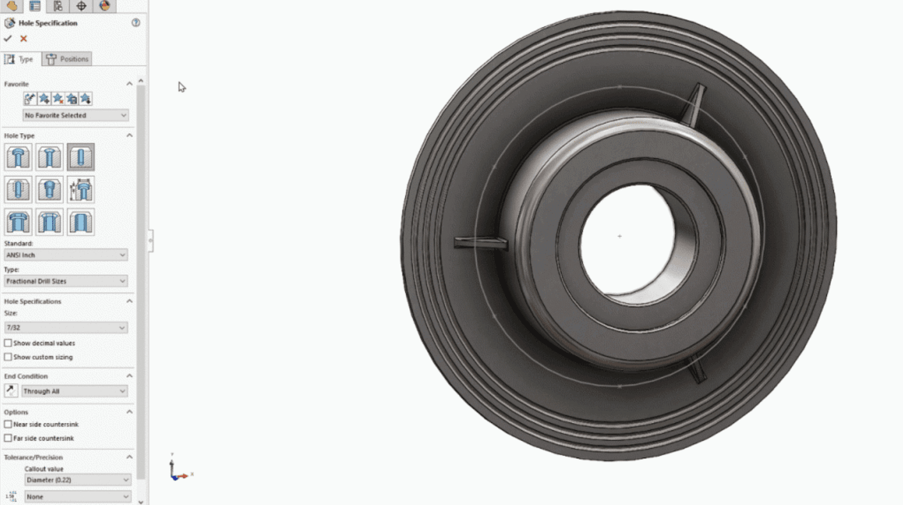
Hole Wizard features for the specified fasteners.
Fillets and chamfers where the design requires them.
Source: SOLIDWORKS Blog
This is a starting structure, not a universal rule. A fillet that defines the primary shape may belong earlier than a small edge treatment.
Give important features descriptive names. “Mounting Holes” and “Cable Clearance” make an unfamiliar model easier to navigate than a long list of default feature names.
Change a Dimension Before Calling the Part Finished
Increase the mounting-hole spacing, alter the material thickness, or adjust the bracket height. Rebuild the part and inspect the result.
Check | What to look for |
|---|---|
Sketch behavior | Geometry changes in the intended direction |
Feature references | Cuts and holes remain attached to suitable geometry |
Rebuild status | No failed features or unresolved errors |
Resulting shape | Required clearances and wall thicknesses remain sensible |
For a family of related brackets, configurations can hold selected dimension and feature variations within the same part document. Use them when the variants share a coherent model structure.
The goal is not simply to produce a bracket that looks correct once. It is to create a model whose next dimensional change remains understandable and controllable.
Assemble Components and Check How They Fit
A finished part does not establish whether the complete design works. Your bracket may need to align with a housing, accept fasteners, and leave enough room for installation. An assembly lets you evaluate those relationships using the actual component geometry.
Create an assembly document and insert the relevant parts. Establish a stable reference component, often by fixing its position or locating it relative to the assembly origin. Then position the remaining components with mates rather than leaving them approximately aligned.
Add Mates That Describe the Intended Relationship
For the bracket and housing, a coincident mate can bring mounting faces together. Concentric mates can align cylindrical holes or fasteners, while a distance mate can define a required offset.
Apply only the relationships the design needs. A component that should rotate must retain the appropriate freedom of movement; a rigid mounting arrangement should not drift when dragged.

Source: SOLIDWORKS Blog
If adding a mate produces an error, inspect the existing relationships before adding more. Conflicting constraints rarely become easier to resolve through additional mates. SOLIDWORKS includes diagnostic tools such as MateXpert within its assembly design tools.
Check More Than Visual Alignment
Rotate the assembly and use section views to inspect concealed interfaces. Two components can appear correctly positioned from one camera angle while overlapping internally.
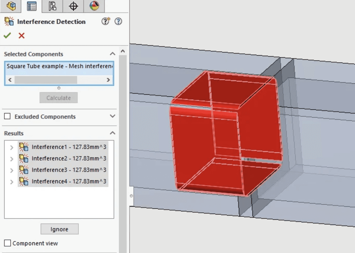
Use Interference Detection to investigate intersecting components, then interpret each result. Some overlaps may be intentional, such as a simplified representation of a threaded connection. Others may reveal an incorrectly positioned fastener or insufficient clearance.
Source: SOLIDWORKS Blog
Before moving on, check:
Whether mounting holes and fastener axes align.
Whether moving components retain their intended travel.
Whether neighboring parts leave the required clearance.
Whether components are fully located or deliberately left movable.
Whether the assembly rebuilds without unresolved mate errors.
These checks support geometric evaluation. They do not establish load capacity, material suitability, or manufacturing tolerance compliance by themselves.
Revisit the Assembly After a Part Changes
Edit the bracket’s hole spacing or thickness, rebuild the assembly, and inspect the connected components again. Watch for mates that fail, unexpected movement, or clearances that disappear.
When using part configurations, confirm that each component references the intended configuration. A valid mate arrangement can still represent the wrong product variant.
This is where a parametric workflow earns its value: a controlled part change flows into the assembly, and the assembly reveals consequences that were not visible in the isolated part.
Produce Drawings That Stay Connected to the Model
A model communicates shape, but manufacturing and inspection often need additional information: dimensions, tolerances, material specifications, and assembly instructions. Create your drawings from the SOLIDWORKS parts and assemblies so the views remain associated with the design.
Choose Views That Explain the Part
Start with the correct drawing template, sheet size, and projection standard. Insert a principal model view, then add projected views that describe the geometry without unnecessary duplication.
For the mounting bracket, a front view may explain the hole pattern while a side view communicates the profile and thickness. Add a section view when internal geometry would otherwise remain ambiguous, or a detail view when a small feature needs more space.
Choose a readable scale. Fitting every view onto one sheet is not useful if the resulting annotations are too small to interpret.

Source: SOLIDWORKS Blog
Add Information the Geometry Cannot Communicate Alone
Dimension the features needed to manufacture and inspect the part. Use suitable hole callouts, datums, tolerances, and notes according to the applicable drawing standard and your organization’s practices.
Avoid treating every model dimension as a necessary drawing dimension. Sketch dimensions describe how the model was constructed; manufacturing dimensions should communicate how the finished component is specified and checked.
A compact drawing review should cover:
Area | Review question |
|---|---|
Dimensions | Is the part sufficiently specified without conflicting information? |
Holes | Are size, depth, thread, and quantity clear where applicable? |
Notes | Are material, finish, and other requirements stated correctly? |
Presentation | Are views, symbols, and annotations legible? |
For an assembly drawing, add a bill of materials and balloons where appropriate. Check component properties and quantities rather than assuming the table is correct simply because it was generated from the assembly.
Verify the Drawing After Model Changes
When a part or assembly changes, rebuild the referenced model and update the drawing. Inspect affected views, dimensions, section lines, and annotations for missing attachments or unintended changes.
Also confirm that each view shows the intended configuration. An updated drawing can still document the wrong variant.
Keep the drawing document alongside its referenced design files. The next section addresses how to preserve those relationships as projects grow and revisions accumulate.
Keep Project References and Revisions Under Control
SOLIDWORKS projects are connected documents, not isolated files. An .SLDASM assembly references component files, and an .SLDDRW drawing references its underlying part or assembly. Copying only the top-level document can leave important geometry behind.
Give Active Projects a Predictable Home
Keep each standalone project in an organized folder on the cloud computer’s Windows disk. Separate working documents from incoming reference material and exported deliverables, while maintaining consistent locations for shared resources.
For example:
The precise folder names matter less than keeping references resolvable. Avoid casually moving or renaming referenced parts in Windows File Explorer. Use SOLIDWORKS reference-aware tools when reorganizing a connected design, then reopen the assembly and drawings to verify the result.
Shared Toolbox components, templates, and material libraries need deliberate file-location settings too.

Source: SOLIDWORKS Blog
Separate Working Changes From Released Revisions
A saved file is not necessarily a released design. Establish a simple revision convention and keep approved delivery packages separate from active development.
Backups protect against loss, but they do not explain which revision is approved or who is editing it. Likewise, Vagon Files supports file transfer; it is not a substitute for CAD-aware revision control.
If your organization uses SOLIDWORKS PDM, follow its check-out, check-in, and release procedures. The cloud workstation needs the appropriate client, permissions, and IT-approved connection to the vault.
Avoid having multiple people independently edit downloaded copies and treating the last upload as the authoritative version. A clear source of truth matters more as assemblies gain components and drawings move toward production.
Match Cloud Performance to Your CAD Work
A complex part rebuild, a crowded assembly, and delayed mouse input can all feel like “slow SOLIDWORKS,” but they have different causes. Choose resources around the operation that needs improvement rather than assuming a larger GPU will fix everything.
Identify the Bottleneck First
What feels slow? | What to investigate |
|---|---|
Features rebuilding after a dimension change | CPU performance, feature dependencies, and rebuild errors |
Opening or updating a large assembly | RAM, storage access, component loading, and references |
Rotating a detailed model | GPU, graphics driver, display settings, and model complexity |
Mouse input and the entire remote desktop | Network latency, connection stability, and region selection |
SOLIDWORKS currently lists 16 GB RAM, with 32 GB recommended, alongside certified graphics hardware and drivers in its system requirements. Treat those figures as a baseline, not a promise that every assembly will fit comfortably into that memory.
Additional applications, drawing views, configurations, and analysis tools can increase demand. Check memory use during a representative working session before deciding whether more capacity is necessary.
Load the Detail Your Task Requires
For larger assemblies, consider Lightweight Components, Large Assembly Settings, and simplified configurations. SpeedPak can reduce the information required to work with selected assemblies while retaining geometry needed for particular operations.
These options have trade-offs. Resolve the necessary components when editing requires their complete feature or mate data. Simplification should support the task, not hide information needed to evaluate the design.
Likewise, investigate rebuild errors and unnecessarily complex dependencies before increasing hardware resources. More capacity will not repair a broken reference.

Source: SOLIDWORKS Blog
Scale Resources and Check the Connection Separately
Vagon’s scalable performance options let you change available computing resources as workload requirements change. Compare configurations using your own parts, assemblies, and drawings rather than an empty document.
Verify the graphics hardware and driver against your SOLIDWORKS release’s support requirements. GPU availability alone does not establish certification.
If Windows menus and keyboard input also feel delayed, examine the connection instead. A nearer region, stable network, or lower streaming resolution may improve responsiveness without changing the CAD workstation’s processing power.
Package Models and Export Manufacturing Deliverables
The right delivery format depends on what the recipient needs to do. A colleague continuing the design needs editable documents and their references. A supplier may need solid geometry and a dimensioned drawing. A 3D-printing workflow may require a mesh.
Keep those outputs separate from the active source files.
Gather Editable Files With Pack and Go
Use Pack and Go when preparing a standalone SOLIDWORKS project for transfer. It gathers related documents into a folder or ZIP file, helping avoid the missing-component problem caused by sending only an assembly.
Review the file list and available options before saving. Include the drawings and supporting resources the recipient actually needs, rather than assuming everything relevant has been collected automatically.

Source: SOLIDWORKS Blog
Confirm the recipient’s SOLIDWORKS version before delivery. Native-file compatibility depends on the releases involved, so agree on the required version and editing expectations in advance.
Match Exports to Their Purpose
Deliverable | Typical purpose | Check before sending |
|---|---|---|
Native SOLIDWORKS package | Continued design and editing | References, configurations, and version compatibility |
STEP | Exchanging solid geometry with other CAD systems | Units, bodies, and exported configuration |
Sharing technical drawings | Sheet size, readability, and current revision | |
STL | Mesh-based workflows such as 3D printing | Units, surface resolution, and mesh suitability |
STEP geometry is not equivalent to the original SOLIDWORKS feature history. Likewise, an STL represents tessellated surfaces rather than an editable parametric solid.
Reopen the Delivery Package
Open the packaged assembly from its delivery location and check that components resolve without relying on files left elsewhere in your workspace. Inspect the drawings and confirm that exports represent the approved configuration.
Use Vagon Files to transfer the checked deliverables to your Googlebook or onward to the recipient. Keep a clearly identified copy of the released package so later changes do not silently overwrite what was delivered.
Final Thoughts
Running SOLIDWORKS on Googlebook does not require replacing your desktop CAD workflow with a viewer or a different modeling application. A compatible cloud Windows workspace lets you develop parametric parts, assemble components, prepare drawings, and package deliverables while using your Googlebook for access.
With the appropriate license and configuration, Vagon Cloud Computer can become your regular design workspace. Set it up around the tools, project standards, and computing resources your work requires, then carry the design from its first sketch to its final delivery.
FAQs
Can you install desktop SOLIDWORKS directly on a Googlebook?
No supported native installation is available for Googlebook. Desktop SOLIDWORKS requires a compatible Windows environment. With a cloud workstation, the application runs remotely while your Googlebook provides browser-based access to the Windows desktop.
Is SOLIDWORKS xDesign the same as desktop SOLIDWORKS?
No. SOLIDWORKS xDesign is a separate browser-native CAD application. Desktop SOLIDWORKS runs as installed Windows software. Choose based on the modeling tools, file workflows, and integrations you need, rather than assuming that both products provide identical capabilities.
Does Vagon include a SOLIDWORKS license?
No. Vagon supplies the cloud computer; you or your organization supplies the SOLIDWORKS entitlement. Confirm that your license permits the proposed deployment and use its approved activation or sign-in method. Company network licenses may also require administrator-configured connectivity.
Is SOLIDWORKS available as a preinstalled Vagon application?
SOLIDWORKS is not currently listed in Vagon’s preinstalled application library. Install it manually inside the Windows workspace using your official download, platform installation process, or company deployment package. Check the catalog again when creating your computer because availability can change.
Can you create new parts and assemblies rather than only view files?
Yes. When desktop SOLIDWORKS is installed, licensed, and functioning correctly, you can create parts, build assemblies, and prepare drawings. Remote access does not turn the application into a viewer. Available features still depend on your SOLIDWORKS edition and installed products.
Can you use SOLIDWORKS Simulation or Visualize?
Potentially, but neither should be assumed to be included or compatible simply because SOLIDWORKS launches. Each product needs the appropriate entitlement and a suitable configuration. Check its specific hardware, graphics, and virtualization requirements before selecting resources or planning production work.
Can a cloud workstation connect to a company PDM vault?
It can serve as a PDM client when your organization approves and configures the connection. You need the appropriate client version, vault permissions, licensing, and network access. Vagon Files does not replace the PDM vault or its revision-control procedures.
Can you use this setup without an internet connection?
No. Your Googlebook needs an active connection to interact with the cloud workstation. Save your work regularly, and distinguish closing the browser from stopping the computer. Follow the service’s controls when ending a session or shutting down the workspace.
Designing a mechanical part involves more than getting its shape right. Hole positions need to remain consistent when dimensions change, components need to fit together, and drawings need to reflect the latest model. If you use a Googlebook, the challenge is finding a workspace where you can carry out that entire process with desktop SOLIDWORKS.
The Windows application does not install natively on Googlebook. However, you can access it through a remote Windows computer that handles the modeling, assembly calculations, and graphics processing while your Googlebook displays the workspace and sends your keyboard and mouse input.
Vagon Cloud Computer provides that approach: a Windows workspace where you can install SOLIDWORKS, configure your design tools, and develop projects from initial sketches through manufacturing deliverables. Your Googlebook becomes the access point rather than the machine responsible for running the CAD software.
You still need a valid SOLIDWORKS license and a Windows configuration that meets your chosen release’s system requirements. With those foundations in place and a stable internet connection, you can build new parts, manage assemblies, prepare drawings, and organize the files your next design depends on.
Source: SOLIDWORKS Blog
Desktop SOLIDWORKS, Cloud Services, or xDesign?
Before setting up your workspace, distinguish between accessing desktop SOLIDWORKS through a browser and using a CAD application built to run in one. Both can involve cloud services, but they provide different working environments.
Option | What you are using | Where the CAD application runs |
|---|---|---|
Desktop SOLIDWORKS | Installed software for parts, assemblies, and drawings | A Windows computer |
Desktop SOLIDWORKS with Cloud Services | Installed CAD software with connected sharing and data-management services | A Windows computer |
SOLIDWORKS xDesign | A separate browser-native CAD application | A cloud-based environment accessed through a browser |
Desktop SOLIDWORKS on Vagon | The installed Windows application accessed remotely | Your Vagon cloud computer |
The phrase “with Cloud Services” does not mean desktop SOLIDWORKS becomes a browser-native application. Depending on your SOLIDWORKS license, installation and sign-in methods differ, but the desktop software still needs a compatible Windows environment.
SOLIDWORKS xDesign takes a different approach. It provides browser-based design tools and deserves consideration if that workflow suits your needs. However, you should not assume it reproduces every desktop feature, add-in, or native-file editing workflow.
Source: SOLIDWORKS Blog
For users who need the desktop FeatureManager, existing SOLIDWORKS templates, native parts and assemblies, or specific Windows-based tools, a remote workstation is the relevant route. With Vagon, the browser provides access to that workstation. SOLIDWORKS itself runs inside Windows, rather than being installed on your Googlebook or replaced by a browser-based viewer.
Set Up Your SOLIDWORKS Workspace on Vagon
The setup brings together three things: your cloud computer, your SOLIDWORKS installation, and the files and settings you use for design. Configure these once, then use the workspace for new projects and ongoing work.
1. Create Your Cloud Computer
Create a Vagon Cloud Computer and choose an available region near your location to help reduce connection latency. Select resources appropriate for your work, allowing more memory for complex assemblies and other applications running alongside SOLIDWORKS.
Open the Windows workspace through your Googlebook’s browser. Before installing software, check the actual Windows edition and version against the requirements for your chosen SOLIDWORKS release. A remote Windows computer is not automatically a supported configuration for every release.
2. Confirm Your License and Installation Method
Use your own valid SOLIDWORKS entitlement. Vagon provides the computer, not a SOLIDWORKS subscription.
Your license type determines how you install and authorize the application. A named-user installation, machine-locked license, and SolidNetWork license can require different steps. For a company-managed license, confirm the cloud deployment with your administrator or reseller, including any required connection to a license server.
3. Install SOLIDWORKS From Your Approved Source
SOLIDWORKS is not currently listed in Vagon’s preinstalled application library. Install it inside the Windows workspace using your official download, platform-based installation method, or company deployment package.
Choose the release and service pack required by your projects and collaborators. Add only the products you need, such as Toolbox or licensed analysis tools. If your organization uses PDM, coordinate the client installation and vault access with IT.
After installation, launch SOLIDWORKS and confirm that licensing works before transferring a complete project library.
4. Bring In Files and Configure Your Workspace
Use Vagon Files to transfer existing project packages, reference documents, and custom resources. Place active CAD projects in an organized folder on the cloud computer’s Windows disk, keeping assembly references together.
For new work, configure your part, assembly, and drawing templates, document units, material libraries, and file locations. Then create a simple part, save it, close it, and reopen it. This confirms that the basic workspace is ready before you build a more involved design.
Build Parametric Parts That Survive Design Changes
Once SOLIDWORKS is running, start with a part whose dimensions you can deliberately change. A mounting bracket is a useful example: its thickness, mounting-hole spacing, and overall height should remain editable without forcing you to rebuild the geometry manually.
The modeling tools work inside your Windows workspace. Your Googlebook provides access to the sketch, FeatureManager tree, and graphics area.
Establish the Design Intent in Your Sketch
Create a new part using the appropriate template and confirm its units. Choose a reference plane that makes sense for the bracket’s orientation, then position the initial profile relative to the origin.
Use sketch relations to describe how geometry should behave. Horizontal, vertical, coincident, and symmetric relations preserve relationships; dimensions control the values that need to change.
Source: SOLIDWORKS Blog
For example, centering two mounting holes around a construction line communicates a different intention from positioning each hole independently from an arbitrary edge.
A fully defined sketch has its geometry constrained by dimensions and relations. That is a useful checkpoint, but the constraints should reflect the intended design. Fixing every entity in place may remove movement without creating a practical parametric model.
Build Features in a Clear Sequence
Turn the profile into a solid with Extruded Boss/Base, then add the remaining features according to how the bracket should be constructed.
A straightforward feature sequence could include:
The main bracket profile and extrusion.
Required cutouts or mounting surfaces.
Hole Wizard features for the specified fasteners.
Fillets and chamfers where the design requires them.
Source: SOLIDWORKS Blog
This is a starting structure, not a universal rule. A fillet that defines the primary shape may belong earlier than a small edge treatment.
Give important features descriptive names. “Mounting Holes” and “Cable Clearance” make an unfamiliar model easier to navigate than a long list of default feature names.
Change a Dimension Before Calling the Part Finished
Increase the mounting-hole spacing, alter the material thickness, or adjust the bracket height. Rebuild the part and inspect the result.
Check | What to look for |
|---|---|
Sketch behavior | Geometry changes in the intended direction |
Feature references | Cuts and holes remain attached to suitable geometry |
Rebuild status | No failed features or unresolved errors |
Resulting shape | Required clearances and wall thicknesses remain sensible |
For a family of related brackets, configurations can hold selected dimension and feature variations within the same part document. Use them when the variants share a coherent model structure.
The goal is not simply to produce a bracket that looks correct once. It is to create a model whose next dimensional change remains understandable and controllable.
Assemble Components and Check How They Fit
A finished part does not establish whether the complete design works. Your bracket may need to align with a housing, accept fasteners, and leave enough room for installation. An assembly lets you evaluate those relationships using the actual component geometry.
Create an assembly document and insert the relevant parts. Establish a stable reference component, often by fixing its position or locating it relative to the assembly origin. Then position the remaining components with mates rather than leaving them approximately aligned.
Add Mates That Describe the Intended Relationship
For the bracket and housing, a coincident mate can bring mounting faces together. Concentric mates can align cylindrical holes or fasteners, while a distance mate can define a required offset.
Apply only the relationships the design needs. A component that should rotate must retain the appropriate freedom of movement; a rigid mounting arrangement should not drift when dragged.
Source: SOLIDWORKS Blog
If adding a mate produces an error, inspect the existing relationships before adding more. Conflicting constraints rarely become easier to resolve through additional mates. SOLIDWORKS includes diagnostic tools such as MateXpert within its assembly design tools.
Check More Than Visual Alignment
Rotate the assembly and use section views to inspect concealed interfaces. Two components can appear correctly positioned from one camera angle while overlapping internally.
Use Interference Detection to investigate intersecting components, then interpret each result. Some overlaps may be intentional, such as a simplified representation of a threaded connection. Others may reveal an incorrectly positioned fastener or insufficient clearance.
Source: SOLIDWORKS Blog
Before moving on, check:
Whether mounting holes and fastener axes align.
Whether moving components retain their intended travel.
Whether neighboring parts leave the required clearance.
Whether components are fully located or deliberately left movable.
Whether the assembly rebuilds without unresolved mate errors.
These checks support geometric evaluation. They do not establish load capacity, material suitability, or manufacturing tolerance compliance by themselves.
Revisit the Assembly After a Part Changes
Edit the bracket’s hole spacing or thickness, rebuild the assembly, and inspect the connected components again. Watch for mates that fail, unexpected movement, or clearances that disappear.
When using part configurations, confirm that each component references the intended configuration. A valid mate arrangement can still represent the wrong product variant.
This is where a parametric workflow earns its value: a controlled part change flows into the assembly, and the assembly reveals consequences that were not visible in the isolated part.
Produce Drawings That Stay Connected to the Model
A model communicates shape, but manufacturing and inspection often need additional information: dimensions, tolerances, material specifications, and assembly instructions. Create your drawings from the SOLIDWORKS parts and assemblies so the views remain associated with the design.
Choose Views That Explain the Part
Start with the correct drawing template, sheet size, and projection standard. Insert a principal model view, then add projected views that describe the geometry without unnecessary duplication.
For the mounting bracket, a front view may explain the hole pattern while a side view communicates the profile and thickness. Add a section view when internal geometry would otherwise remain ambiguous, or a detail view when a small feature needs more space.
Choose a readable scale. Fitting every view onto one sheet is not useful if the resulting annotations are too small to interpret.
Source: SOLIDWORKS Blog
Add Information the Geometry Cannot Communicate Alone
Dimension the features needed to manufacture and inspect the part. Use suitable hole callouts, datums, tolerances, and notes according to the applicable drawing standard and your organization’s practices.
Avoid treating every model dimension as a necessary drawing dimension. Sketch dimensions describe how the model was constructed; manufacturing dimensions should communicate how the finished component is specified and checked.
A compact drawing review should cover:
Area | Review question |
|---|---|
Dimensions | Is the part sufficiently specified without conflicting information? |
Holes | Are size, depth, thread, and quantity clear where applicable? |
Notes | Are material, finish, and other requirements stated correctly? |
Presentation | Are views, symbols, and annotations legible? |
For an assembly drawing, add a bill of materials and balloons where appropriate. Check component properties and quantities rather than assuming the table is correct simply because it was generated from the assembly.
Verify the Drawing After Model Changes
When a part or assembly changes, rebuild the referenced model and update the drawing. Inspect affected views, dimensions, section lines, and annotations for missing attachments or unintended changes.
Also confirm that each view shows the intended configuration. An updated drawing can still document the wrong variant.
Keep the drawing document alongside its referenced design files. The next section addresses how to preserve those relationships as projects grow and revisions accumulate.
Keep Project References and Revisions Under Control
SOLIDWORKS projects are connected documents, not isolated files. An .SLDASM assembly references component files, and an .SLDDRW drawing references its underlying part or assembly. Copying only the top-level document can leave important geometry behind.
Give Active Projects a Predictable Home
Keep each standalone project in an organized folder on the cloud computer’s Windows disk. Separate working documents from incoming reference material and exported deliverables, while maintaining consistent locations for shared resources.
For example:
The precise folder names matter less than keeping references resolvable. Avoid casually moving or renaming referenced parts in Windows File Explorer. Use SOLIDWORKS reference-aware tools when reorganizing a connected design, then reopen the assembly and drawings to verify the result.
Shared Toolbox components, templates, and material libraries need deliberate file-location settings too.
Source: SOLIDWORKS Blog
Separate Working Changes From Released Revisions
A saved file is not necessarily a released design. Establish a simple revision convention and keep approved delivery packages separate from active development.
Backups protect against loss, but they do not explain which revision is approved or who is editing it. Likewise, Vagon Files supports file transfer; it is not a substitute for CAD-aware revision control.
If your organization uses SOLIDWORKS PDM, follow its check-out, check-in, and release procedures. The cloud workstation needs the appropriate client, permissions, and IT-approved connection to the vault.
Avoid having multiple people independently edit downloaded copies and treating the last upload as the authoritative version. A clear source of truth matters more as assemblies gain components and drawings move toward production.
Match Cloud Performance to Your CAD Work
A complex part rebuild, a crowded assembly, and delayed mouse input can all feel like “slow SOLIDWORKS,” but they have different causes. Choose resources around the operation that needs improvement rather than assuming a larger GPU will fix everything.
Identify the Bottleneck First
What feels slow? | What to investigate |
|---|---|
Features rebuilding after a dimension change | CPU performance, feature dependencies, and rebuild errors |
Opening or updating a large assembly | RAM, storage access, component loading, and references |
Rotating a detailed model | GPU, graphics driver, display settings, and model complexity |
Mouse input and the entire remote desktop | Network latency, connection stability, and region selection |
SOLIDWORKS currently lists 16 GB RAM, with 32 GB recommended, alongside certified graphics hardware and drivers in its system requirements. Treat those figures as a baseline, not a promise that every assembly will fit comfortably into that memory.
Additional applications, drawing views, configurations, and analysis tools can increase demand. Check memory use during a representative working session before deciding whether more capacity is necessary.
Load the Detail Your Task Requires
For larger assemblies, consider Lightweight Components, Large Assembly Settings, and simplified configurations. SpeedPak can reduce the information required to work with selected assemblies while retaining geometry needed for particular operations.
These options have trade-offs. Resolve the necessary components when editing requires their complete feature or mate data. Simplification should support the task, not hide information needed to evaluate the design.
Likewise, investigate rebuild errors and unnecessarily complex dependencies before increasing hardware resources. More capacity will not repair a broken reference.
Source: SOLIDWORKS Blog
Scale Resources and Check the Connection Separately
Vagon’s scalable performance options let you change available computing resources as workload requirements change. Compare configurations using your own parts, assemblies, and drawings rather than an empty document.
Verify the graphics hardware and driver against your SOLIDWORKS release’s support requirements. GPU availability alone does not establish certification.
If Windows menus and keyboard input also feel delayed, examine the connection instead. A nearer region, stable network, or lower streaming resolution may improve responsiveness without changing the CAD workstation’s processing power.
Package Models and Export Manufacturing Deliverables
The right delivery format depends on what the recipient needs to do. A colleague continuing the design needs editable documents and their references. A supplier may need solid geometry and a dimensioned drawing. A 3D-printing workflow may require a mesh.
Keep those outputs separate from the active source files.
Gather Editable Files With Pack and Go
Use Pack and Go when preparing a standalone SOLIDWORKS project for transfer. It gathers related documents into a folder or ZIP file, helping avoid the missing-component problem caused by sending only an assembly.
Review the file list and available options before saving. Include the drawings and supporting resources the recipient actually needs, rather than assuming everything relevant has been collected automatically.
Source: SOLIDWORKS Blog
Confirm the recipient’s SOLIDWORKS version before delivery. Native-file compatibility depends on the releases involved, so agree on the required version and editing expectations in advance.
Match Exports to Their Purpose
Deliverable | Typical purpose | Check before sending |
|---|---|---|
Native SOLIDWORKS package | Continued design and editing | References, configurations, and version compatibility |
STEP | Exchanging solid geometry with other CAD systems | Units, bodies, and exported configuration |
Sharing technical drawings | Sheet size, readability, and current revision | |
STL | Mesh-based workflows such as 3D printing | Units, surface resolution, and mesh suitability |
STEP geometry is not equivalent to the original SOLIDWORKS feature history. Likewise, an STL represents tessellated surfaces rather than an editable parametric solid.
Reopen the Delivery Package
Open the packaged assembly from its delivery location and check that components resolve without relying on files left elsewhere in your workspace. Inspect the drawings and confirm that exports represent the approved configuration.
Use Vagon Files to transfer the checked deliverables to your Googlebook or onward to the recipient. Keep a clearly identified copy of the released package so later changes do not silently overwrite what was delivered.
Final Thoughts
Running SOLIDWORKS on Googlebook does not require replacing your desktop CAD workflow with a viewer or a different modeling application. A compatible cloud Windows workspace lets you develop parametric parts, assemble components, prepare drawings, and package deliverables while using your Googlebook for access.
With the appropriate license and configuration, Vagon Cloud Computer can become your regular design workspace. Set it up around the tools, project standards, and computing resources your work requires, then carry the design from its first sketch to its final delivery.
FAQs
Can you install desktop SOLIDWORKS directly on a Googlebook?
No supported native installation is available for Googlebook. Desktop SOLIDWORKS requires a compatible Windows environment. With a cloud workstation, the application runs remotely while your Googlebook provides browser-based access to the Windows desktop.
Is SOLIDWORKS xDesign the same as desktop SOLIDWORKS?
No. SOLIDWORKS xDesign is a separate browser-native CAD application. Desktop SOLIDWORKS runs as installed Windows software. Choose based on the modeling tools, file workflows, and integrations you need, rather than assuming that both products provide identical capabilities.
Does Vagon include a SOLIDWORKS license?
No. Vagon supplies the cloud computer; you or your organization supplies the SOLIDWORKS entitlement. Confirm that your license permits the proposed deployment and use its approved activation or sign-in method. Company network licenses may also require administrator-configured connectivity.
Is SOLIDWORKS available as a preinstalled Vagon application?
SOLIDWORKS is not currently listed in Vagon’s preinstalled application library. Install it manually inside the Windows workspace using your official download, platform installation process, or company deployment package. Check the catalog again when creating your computer because availability can change.
Can you create new parts and assemblies rather than only view files?
Yes. When desktop SOLIDWORKS is installed, licensed, and functioning correctly, you can create parts, build assemblies, and prepare drawings. Remote access does not turn the application into a viewer. Available features still depend on your SOLIDWORKS edition and installed products.
Can you use SOLIDWORKS Simulation or Visualize?
Potentially, but neither should be assumed to be included or compatible simply because SOLIDWORKS launches. Each product needs the appropriate entitlement and a suitable configuration. Check its specific hardware, graphics, and virtualization requirements before selecting resources or planning production work.
Can a cloud workstation connect to a company PDM vault?
It can serve as a PDM client when your organization approves and configures the connection. You need the appropriate client version, vault permissions, licensing, and network access. Vagon Files does not replace the PDM vault or its revision-control procedures.
Can you use this setup without an internet connection?
No. Your Googlebook needs an active connection to interact with the cloud workstation. Save your work regularly, and distinguish closing the browser from stopping the computer. Follow the service’s controls when ending a session or shutting down the workspace.
Get Beyond Your Computer Performance
Run applications on your cloud computer with the latest generation hardware. No more crashes or lags.

Trial includes 1 hour usage + 7 days of storage.
Summarize with AI
Ready to focus on your creativity?
Vagon gives you the ability to create & render projects, collaborate, and stream applications with the power of the best hardware.
Vagon Blog
Run heavy applications on any device with
your personal computer on the cloud.
San Francisco, California
Solutions
Vagon Teams
Vagon Streams
Use Cases
Resources
Vagon Blog
How to Run Premiere Pro on Googlebook: Editing Guide
How to Run Revit on Googlebook: Complete BIM Guide
How to Run SOLIDWORKS on Googlebook: Complete CAD Guide
How to Run AutoCAD on Googlebook
How to Run Photoshop on Googlebook
How to Use SketchUp With Codex: MCP and Computer Use
How to Use SketchUp With Claude: MCP and Computer Use
How to Use ComfyUI With Codex: MCP and Computer Use
How to Use Godot With Codex: MCP & Computer Use Guide
Vagon Blog
Run heavy applications on any device with
your personal computer on the cloud.
San Francisco, California
Solutions
Vagon Teams
Vagon Streams
Use Cases
Resources
Vagon Blog
How to Run Premiere Pro on Googlebook: Editing Guide
How to Run Revit on Googlebook: Complete BIM Guide
How to Run SOLIDWORKS on Googlebook: Complete CAD Guide
How to Run AutoCAD on Googlebook
How to Run Photoshop on Googlebook
How to Use SketchUp With Codex: MCP and Computer Use
How to Use SketchUp With Claude: MCP and Computer Use
How to Use ComfyUI With Codex: MCP and Computer Use
How to Use Godot With Codex: MCP & Computer Use Guide
Vagon Blog
Run heavy applications on any device with
your personal computer on the cloud.
San Francisco, California
Solutions
Vagon Teams
Vagon Streams
Use Cases
Resources
Vagon Blog