Instant Connection for Pixel Streaming
— New Feature Automated Setup
How to Use SolidWorks for 3D Printing: STL Export, Settings & Workflow Guide
How to Use SolidWorks for 3D Printing: STL Export, Settings & Workflow Guide
DigitalArt
How to Use SolidWorks for 3D Printing: STL Export, Settings & Workflow Guide
How to Use SolidWorks for 3D Printing: STL Export, Settings & Workflow Guide
Table of Contents
The first time you 3D print a SolidWorks model feels like it should be simple.
You finish the design, check the dimensions, admire the clean surfaces. Everything looks perfect on the screen. At that point most people think the job is basically done. Export the file, send it to the printer, grab a coffee, and wait for the part to appear.
I thought the same thing.
My first print looked nothing like the model. The cylinder had weird flat edges. The bolt hole was just slightly too small. The bottom surface warped enough to make the whole piece unusable.
The SolidWorks model itself was fine. The problem happened somewhere between the CAD file and the printer.
That gap is where many SolidWorks users run into trouble.

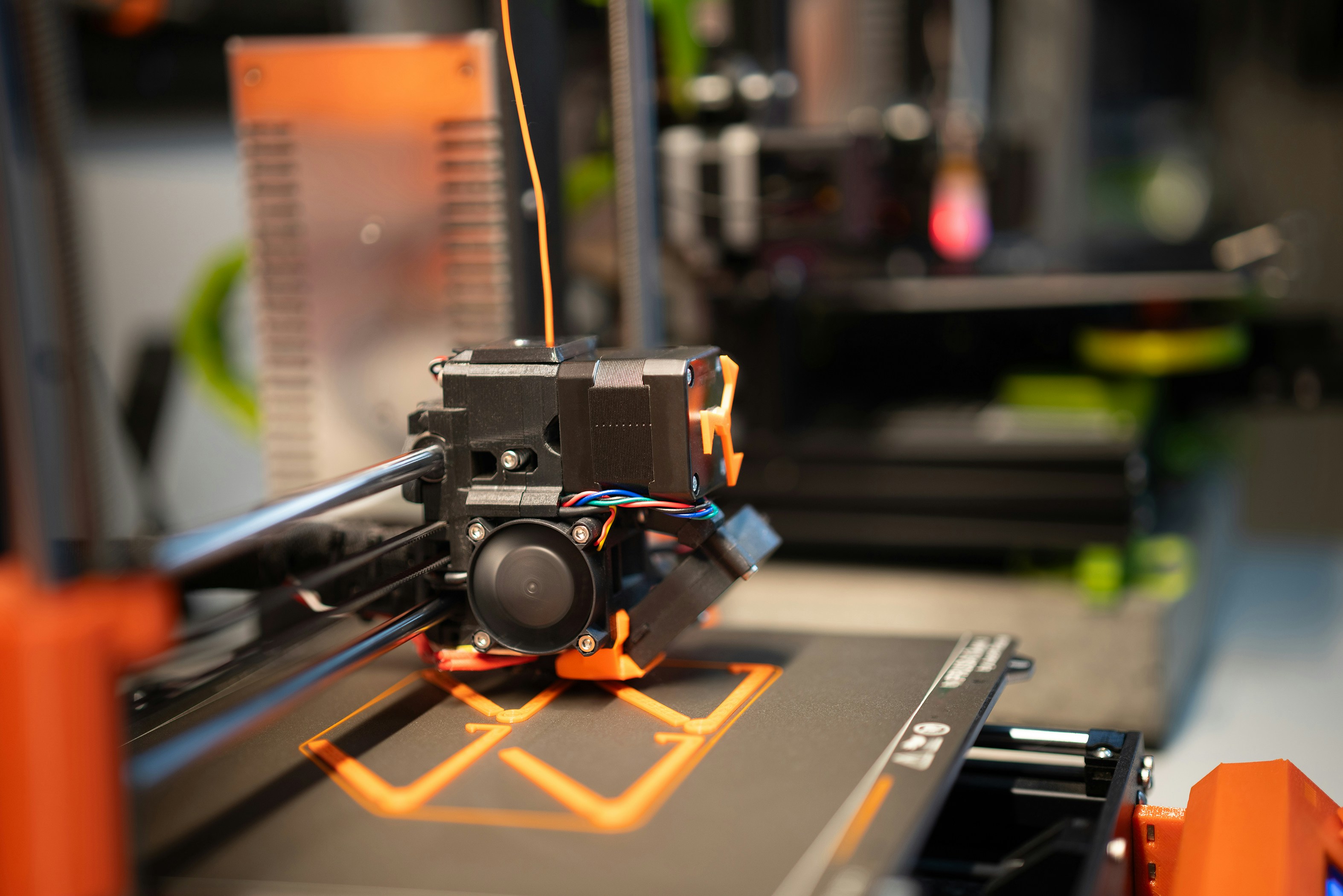
SolidWorks models are built with precise mathematical surfaces. Perfect arcs, exact dimensions, smooth curvature. But 3D printers don’t read that kind of geometry. They rely on mesh files made of thousands of tiny triangles. When you export your design as an STL, SolidWorks converts those smooth surfaces into that triangle mesh.
And the settings you choose during that conversion matter more than most people expect.
Too few triangles and curves start looking faceted. Too many and the file becomes unnecessarily heavy. Units, tolerances, and orientation can also affect whether a print succeeds or quietly fails.
Small settings. Big consequences.
So before sending your next model to a printer, it helps to understand what’s actually happening in that export step.
Let’s walk through the real workflow.
What Actually Happens When You 3D Print a SolidWorks Model
Here’s something that surprises a lot of SolidWorks users the first time they look into it.
Your CAD model isn’t what the printer actually prints.
SolidWorks works with parametric geometry. Every face is defined by math. A circle is a perfect circle. A fillet is a smooth curve calculated by the software. That precision is exactly why engineers like using SolidWorks in the first place.
3D printers, on the other hand, don’t understand that kind of geometry at all.
They read mesh files.
A mesh is basically a surface built from thousands of small triangles stitched together. Instead of a mathematically perfect cylinder, the printer sees something closer to a many-sided shape made of flat faces. If there are enough triangles, it looks smooth. If there aren’t… you start seeing the edges.
This conversion from CAD geometry to triangles happens when you export your model, usually as an STL file.
STL has been around since the late 1980s and somehow it’s still the most common format for 3D printing. There are newer options like 3MF and AMF that store more information such as color, materials, and units. In practice though, most slicing software and printers still expect STL files.
So the workflow usually looks like this:
Create your model in SolidWorks
Export the model as an STL mesh
Import that mesh into slicing software like Cura or PrusaSlicer
Generate toolpaths for the printer
Send the instructions to the printer

The critical step is number two.
That’s where SolidWorks decides how detailed the mesh will be. Too coarse and curved surfaces look rough. Too detailed and you end up with giant files that slow down slicing software for no real benefit.
I’ve seen users export a simple bracket and accidentally generate a 300 MB STL file. Not fun when your slicer freezes every time you rotate the model.
The key takeaway here is simple.
3D printing isn’t just about designing the part. It’s about translating the CAD model into something a printer can understand without losing the shape you worked so hard to create.
Once you understand that translation step, the rest of the workflow becomes much easier to control.
Designing SolidWorks Models That Actually Print Well
One thing I’ve noticed over the years is that good CAD models aren’t always good 3D printing models.
SolidWorks lets you design almost anything. Ultra-thin walls. Perfectly sharp edges. Tiny mechanical features. On screen it all looks great.
The printer may strongly disagree.
3D printers have physical limitations. Plastic needs space to flow. Layers need something to sit on. And tolerances behave very differently compared to machined parts.
If you keep those limits in mind while modeling, your success rate jumps dramatically.
Wall thickness matters more than people expect
A common mistake is designing walls that are simply too thin.
Most desktop FDM printers use a 0.4 mm nozzle, which means walls usually need to be at least 1.0 to 1.2 mm thick to print reliably. Thinner features might appear in the slicer but fail halfway through the print.
In my experience, designing walls around 1.5 to 2 mm gives much more consistent results. Stronger parts too.
Overhangs can ruin a print
Another thing SolidWorks doesn’t warn you about is overhang angles.
If a surface extends outward too steeply, the printer starts laying filament in mid-air. That rarely ends well. Most printers handle angles up to about 45 degrees without supports. Anything steeper usually needs them.
So when modeling parts, it helps to ask a simple question.
“Can this layer sit on something underneath it?”
If the answer is no, expect support structures later.

Moving parts need extra tolerance
CAD assemblies can be incredibly precise. Two surfaces can sit exactly 0.00 mm apart and look perfectly fine.
3D printing doesn’t work like that.
Plastic expands slightly during printing, and small inaccuracies accumulate layer by layer. If you design moving parts like hinges or sliding components, you’ll usually want at least 0.2 to 0.4 mm of clearance between surfaces.
Otherwise the parts fuse together.
I learned that the hard way while printing a hinge that was supposed to move freely. The printer turned it into a very solid brick.
Fillets are your friend
Sharp edges may look clean in CAD, but they’re not always ideal for printed parts.
Adding fillets or chamfers does a few helpful things:
Improves structural strength
Reduces stress points
Helps layers transition more smoothly
Even small fillets can make printed parts noticeably stronger.
One small mindset shift helps a lot
When you design for machining, you usually start with manufacturing constraints.
3D printing works the same way.
Once you start thinking about layer direction, wall thickness, and overhangs while modeling, you’ll spend far less time troubleshooting prints later. And that’s where SolidWorks becomes incredibly powerful for rapid prototyping.
If you want to experiment with ready-made models before designing your own parts, this list of 3D model databases for visualization and 3D printing is a great place to start.
Preparing the Model for 3D Printing Inside SolidWorks
Before exporting anything, SolidWorks actually gives you a useful tool that many users skip entirely.
It’s called Print3D.
You can find it under File → Print3D, and it’s designed to help check whether your model will physically fit and orient correctly on a printer’s build plate. It’s not a slicer. Think of it more like a quick sanity check before exporting the file.
A surprising number of problems can be spotted right here.
First step: match your printer’s build volume
When you open the Print3D tool, SolidWorks lets you define the dimensions of the printer bed. You can either choose from preset printers or manually enter the size.
For example, a typical desktop printer might have something like:
220 × 220 × 250 mm build volume
If your part exceeds those dimensions, SolidWorks will immediately show the problem. That alone can save a lot of frustration.
I’ve seen people design a beautiful enclosure only to realize later it’s 10 mm wider than the printer bed.

Orientation affects everything
This is where things start getting interesting.
The orientation of a model has a huge effect on how it prints. It impacts:
support structures
surface quality
strength of the part
total print time
A tall part standing upright might look correct visually, but printing it that way could mean hours of unnecessary supports. Rotating it 90 degrees can sometimes cut the print time in half.
SolidWorks lets you rotate and position the model directly on the virtual build plate, which makes it easier to experiment before exporting.
Fit checks are surprisingly helpful
Another feature inside Print3D is the “Check print bed” option, which confirms whether the part fits within the printer’s working area.
It sounds basic. But catching a scaling issue here is much better than discovering it in the slicer after you’ve already exported the file.
Why this step is often skipped
Most SolidWorks users jump straight to Save As → STL and move on.
That works most of the time. But spending thirty seconds inside the Print3D tool can help you think about orientation and scale before the model ever leaves SolidWorks.
And that leads directly to the next step. The one that quietly controls how smooth or ugly your printed part will look.
Exporting the STL file.
If you’re still deciding on hardware for your setup, this guide to the best 3D printers in 2026 highlights some of the most capable machines available right now.
Exporting STL Files From SolidWorks
If there’s one step where SolidWorks users accidentally sabotage their prints, it’s this one.
Exporting the STL file sounds trivial. It’s just File → Save As → STL, right?
Technically yes. But those export settings control how your CAD model gets converted into the mesh that the printer will actually read. And if the settings are off, your perfect model can turn into something… questionable.
Start with the basic export process
The usual workflow looks like this:
Go to File → Save As
Change the file type to STL (*.stl)
Click Options
Adjust the export settings
Save the file
That little Options button is where all the important decisions live.
Binary vs ASCII
SolidWorks gives you two STL file formats.
Binary
ASCII
In almost every case, you want Binary.
ASCII files are human-readable text files. That sounds nice in theory, but it makes the files much larger. A simple model that’s a few megabytes in binary can balloon dramatically in ASCII format.
Binary STL files are smaller, faster to load, and widely supported by slicing software.
Unit selection matters
This is another easy mistake.
STL files themselves don’t actually store unit information. That means the slicer interprets the geometry based on what it assumes the units are.
So if you designed a part in millimeters but export it incorrectly, your slicer might think the model is in inches. Suddenly your 40 mm bracket becomes a tiny speck on the build plate.
Inside the export settings, always confirm the unit system matches your design.
It sounds obvious. It still happens all the time.
The resolution settings are the real story
The most important choice in the STL export window is the resolution.
SolidWorks gives three options:
Coarse
Fine
Custom
Most beginners either leave it on the default or switch to Fine without thinking about it. Sometimes that works. Sometimes it creates unnecessarily heavy files.
The resolution controls how accurately the triangle mesh represents your original CAD surfaces. Smooth curves require more triangles. Flat surfaces require very few.
That’s where the real balancing act begins.
And it deserves its own section, because these two little numbers quietly control the visual quality of your entire print.
If your projects lean more toward architectural or conceptual modeling, you might also find this comparison of AutoCAD and SketchUp helpful.
The STL Resolution Settings That Control Your Print Quality
Inside the STL export settings, there are two numbers that quietly decide how your printed part will look.
Most people glance at them once and move on.
I wouldn’t.
These settings control how SolidWorks converts smooth CAD surfaces into triangles. If the resolution is too low, curves start looking faceted. If it’s too high, the file becomes unnecessarily heavy and your slicer slows down for no real gain.
The two parameters you’ll see are:
Deviation tolerance
Angle tolerance
They sound technical, but the idea is pretty simple.
Deviation tolerance
Deviation controls how far the triangle mesh is allowed to deviate from the original CAD surface.
Lower numbers mean the mesh follows the curve more closely.
For example, imagine exporting a simple cylinder. With a high deviation value, SolidWorks approximates that curve with fewer triangles. The result might look slightly polygonal when printed. With a smaller value, the mesh uses many more triangles and the curve appears smoother.
For most FDM prints, a deviation around 0.01 mm to 0.05 mm works well.
Going much lower rarely improves the final print because the printer’s layer height becomes the limiting factor anyway.
Angle tolerance
Angle tolerance controls how sharply adjacent triangles are allowed to change direction.
Lower values create smoother transitions across curved surfaces. Higher values allow bigger jumps between triangles, which can produce visible facets.
Typical values fall around 5 to 15 degrees depending on how smooth you want the mesh to be.
Why “Fine” isn’t always better
SolidWorks includes a Fine preset, and it’s tempting to use it every time.
Sometimes that’s overkill.
I’ve seen very simple parts exported with extremely high resolution, producing STL files that were 50 or 100 times larger than necessary. The slicer then spends extra time processing geometry that the printer can’t even reproduce.
Remember that most FDM printers operate at layer heights between 0.1 mm and 0.3 mm. If your mesh accuracy is dramatically higher than the printer’s capability, you’re just adding file size without improving the part.
A practical rule of thumb
If the model has smooth curves or organic shapes, use custom settings with moderately fine tolerances.
If the model is mostly flat faces and sharp edges, a lower resolution is often perfectly fine.
Once you find settings that work well with your printer and slicer, save them and reuse them. It saves time and keeps your prints consistent.
With the STL exported properly, the next step happens outside SolidWorks.
Now the model needs to go into a slicer. That’s where the printer instructions are actually generated.
If you’re deciding between different modeling environments for design or visualization work, this comparison of AutoCAD and Blender breaks down where each tool fits best.
Importing Your SolidWorks Model Into a Slicer
Once the STL file is exported, SolidWorks has done its job.
Now the model moves into slicing software, which is where the printer instructions are actually created. The slicer takes your mesh and converts it into thousands of layers and toolpaths that the printer follows step by step.
Think of it as translating the model into the printer’s language.
Popular slicers include:
Ultimaker Cura
PrusaSlicer
Bambu Studio
Simplify3D
They all work in roughly the same way.
First thing to check: scale
When you import the STL into the slicer, the first thing I always look at is size.
Remember earlier when we talked about STL files not storing unit information? This is where that sometimes shows up. If something went wrong during export, your part might appear tiny or absurdly large.
A bracket designed to be 80 mm wide suddenly appears as 3 mm, or the opposite. If that happens, it’s usually just a unit mismatch.
Most slicers let you correct the scale instantly, but ideally you catch it early.
Orientation still matters
The slicer also lets you rotate and reposition the model on the build plate.
Even if you already checked orientation in SolidWorks, this is worth revisiting. Sometimes seeing the supports generated by the slicer changes your strategy.
For example, rotating a model slightly can:
reduce support structures
improve surface quality
shorten the total print time
Small adjustments can make a big difference.

Choosing the core print settings
This is where you start defining how the printer builds the object.
Three settings affect most prints:
Layer height
Typical values range from 0.1 mm to 0.3 mm. Smaller layers produce smoother surfaces but increase print time.
Infill percentage
This controls how solid the inside of the part is. Many functional parts work well around 15–30% infill, while decorative models can go lower.
Supports
If the model has steep overhangs, the slicer will generate temporary support structures to hold up those areas during printing.
Once those settings are configured, the slicer generates the G-code that actually drives the printer.
At that point, your design finally turns into physical layers of plastic.
But before we get too far ahead, it’s worth talking about something almost every SolidWorks user experiences at least once.
The classic mistakes that ruin otherwise good prints.
Problems I See SolidWorks Users Run Into All the Time
After watching a lot of SolidWorks users start experimenting with 3D printing, I’ve noticed a pattern.
The first few prints usually fail for reasons that have nothing to do with the design itself. The model might be perfectly engineered, but small workflow mistakes sneak in during export or slicing.
Most of them are easy to fix once you know what to look for.
The classic unit mismatch
This one happens constantly.
You design a part in millimeters, export the STL, open it in the slicer… and suddenly the model looks microscopic. Or enormous.
The root problem is simple. STL files don’t carry unit data, so the slicer guesses. If the slicer assumes inches while the model was designed in millimeters, everything scales incorrectly.
It’s an easy fix inside the slicer, but it’s better to catch it early so dimensions stay predictable.
Tolerances that are too tight
SolidWorks allows extremely precise fits. Two surfaces can sit perfectly flush with no visible gap.
3D printers aren’t that precise.
Plastic expands slightly as it cools, and layer-by-layer printing introduces tiny inaccuracies. If you design interlocking parts without clearance, they’ll often fuse together.
A safe rule for many desktop printers is 0.2 to 0.4 mm of clearance between moving parts.
Thin features that disappear
Another common issue is thin geometry.
A wall that looks perfectly fine in SolidWorks might be thinner than the printer’s nozzle width. When the slicer processes the model, it may simply ignore that feature because it can’t generate a valid toolpath.
This leads to missing walls, fragile structures, or strange gaps in the print.
Overly detailed meshes
This problem usually starts with STL export settings.
Users switch to extremely fine mesh resolution thinking it will improve print quality. Instead they create huge STL files that slow down the slicer and make previews lag.
Meanwhile the printer itself may only be printing 0.2 mm layers, which means that extra mesh detail isn’t doing anything useful.
Exporting assemblies incorrectly
SolidWorks assemblies can contain many separate parts. When exporting to STL, those parts can sometimes overlap or merge in ways that confuse the slicer.
Sometimes you want to export individual bodies separately. Other times you want a combined mesh.
The important thing is understanding how the slicer will interpret the file.
Most of these issues only happen once or twice. After that, you start spotting them instantly.
And once those basics are under control, you can start using a few more advanced SolidWorks tricks that make printed parts much easier to manage.
If you're exploring different modeling tools beyond SolidWorks, this comparison of Blender and Rhino explains how mesh and NURBS modeling approaches differ.
A Few SolidWorks Tricks That Make 3D Printing Much Easier
Once you get comfortable with the basic workflow, SolidWorks has a few features that can make your 3D printing life noticeably easier. They’re not strictly required, but I’ve found myself using them more and more when preparing models.
Splitting large parts into printable sections
Sooner or later you’ll design something that simply doesn’t fit on your printer’s build plate.
Instead of redesigning the entire model, SolidWorks lets you split the part into multiple bodies. The Split feature or even simple reference planes can divide a large object into smaller sections that print separately.
Later you can glue or mechanically fasten the pieces together.
This trick is especially useful for things like enclosures, large prototypes, or structural parts that exceed your printer’s build volume.
Exporting assemblies more intelligently
Assemblies can behave strangely when exported as a single STL.
Sometimes parts intersect slightly. Sometimes the slicer merges bodies in unexpected ways. In other cases, moving components that should remain separate become fused into one mesh.
A safer approach is often to export individual components as separate STL files and arrange them in the slicer. That gives you much more control over orientation and spacing.
It also lets you print only the pieces that actually changed after a design revision.
Simplifying geometry before export
Not every feature in a SolidWorks model needs to appear in the printed part.
Tiny fillets, cosmetic details, or extremely small holes can sometimes create unnecessary mesh complexity. In some cases they even produce slicing artifacts.
If a feature is smaller than the printer can realistically reproduce, it may be worth suppressing it before exporting the STL.
The result is a cleaner mesh and faster slicing.
Printing threaded parts
Threads are a common question.
Technically you can model full threads in SolidWorks and print them directly, but for many printers the results are inconsistent. Very small threads especially tend to struggle.
In practice, slightly oversized threads or printed holes designed to accept metal inserts often work better.
Small adjustments save a lot of frustration
None of these tricks are complicated. They’re just small workflow adjustments.
But they make the entire design-to-print process smoother, especially once you start working on larger assemblies or more complex prototypes.
At some point though, another challenge tends to appear. Not in the model itself, but in the hardware running SolidWorks.
When Your SolidWorks Projects Start Outgrowing Your Hardware
There’s a point where SolidWorks projects start getting heavier than the machine you’re running them on.
It usually happens gradually.
At first you’re designing simple brackets or small prototype parts. Everything runs smoothly. Rebuilds are quick, STL exports take seconds, and slicing is instant.
Then the projects grow.
Now you’re working on multi-part assemblies. Complex surfaces. High-resolution meshes so curved parts print smoothly. Maybe you’re exporting several STL files at once for a prototype with multiple components.
Suddenly the laptop that handled your early projects starts struggling a bit.
Rotating large models gets laggy. STL exports take longer than expected. Slicers slow down when processing dense meshes. It’s not catastrophic, but it’s definitely noticeable.
This is where some SolidWorks users start upgrading hardware. Faster CPU. More RAM. A stronger GPU.
That works. But it’s also expensive and not always practical if you’re working from different locations or collaborating with a team.
Another option that’s been gaining traction is using Vagon Cloud Computer.
Instead of relying on your local machine, Vagon lets you run demanding software like **SolidWorks on powerful cloud machines with dedicated GPUs. You connect through your browser and access a workstation that’s significantly stronger than most laptops.
For designers working with heavier assemblies or high-resolution models, that can make a noticeable difference. STL exports happen faster. Large models stay responsive. And you can open the same workspace from almost any device.
It also makes collaboration easier. Sharing a powerful environment with teammates removes the usual “does your computer handle this file?” problem that sometimes shows up with complex CAD projects.
It’s not something every SolidWorks user needs right away.
But once your 3D printing projects start involving larger assemblies, detailed surfaces, or frequent iterations, having access to a stronger machine without managing the hardware yourself can be surprisingly helpful.
The Real Magic of Using SolidWorks for 3D Printing
There’s something oddly satisfying about watching a SolidWorks model turn into a physical object.
You spend time refining sketches, adjusting dimensions, tweaking fillets. At some point it all lives only on the screen. Lines, surfaces, numbers.
Then a few minutes later a printer starts laying down plastic layer by layer, and suddenly that digital model exists in the real world.
That feedback loop is what makes 3D printing so powerful for SolidWorks users.
You can design something in the morning, print a prototype in the afternoon, notice a flaw, and revise the model before the day is over. That kind of iteration used to take days or even weeks when parts had to be machined externally.
Now it’s just part of the normal workflow.
Of course, getting reliable prints depends on understanding the steps between CAD and the printer. Designing with print limitations in mind. Exporting STL files with sensible resolution. Choosing the right orientation and slicer settings.
None of these steps are particularly difficult. They just require a bit of awareness.
Once the workflow becomes second nature, SolidWorks turns into an incredibly effective tool for rapid prototyping. Ideas move from sketches to real objects faster than most designers expect the first time they try it.
And honestly, that moment when a design becomes something you can actually hold never really gets old.
If you're curious how a mesh-based workflow compares to CAD modeling, you might also want to check out this guide on how to use Blender for 3D printing.
FAQs
1. Can SolidWorks export files directly for 3D printing?
Yes. SolidWorks can export models directly as STL files, which are the most commonly used format for 3D printing. The usual workflow is simple. You export the STL file from SolidWorks and then import it into a slicer like Cura, PrusaSlicer, or Bambu Studio. The slicer converts the model into the layer-by-layer instructions that your printer follows.
2. Why does my SolidWorks model appear the wrong size in the slicer?
This usually happens because STL files do not store unit information. If your model was designed in millimeters but the slicer assumes inches, the part will appear dramatically smaller or larger than expected. The fix is usually simple. Most slicers allow you to scale the model instantly, but it’s always a good idea to double check the units when exporting the STL.
3. What STL resolution should I use?
For most 3D printing projects, moderate resolution settings work best. Extremely high resolution can create very large files without improving the final printed part. In many cases, a deviation tolerance around 0.01 to 0.05 mm and an angle tolerance between about 5 and 15 degrees produces smooth results without slowing down the slicing process.
4. Do I need a powerful computer for SolidWorks 3D printing workflows?
Not necessarily. Many smaller parts and prototypes run fine on typical machines. But once models become larger or assemblies get more complex, performance can start to matter. That’s why some designers run heavier projects using cloud workstations like Vagon, which allows SolidWorks to run on stronger remote hardware when local machines start struggling.
The first time you 3D print a SolidWorks model feels like it should be simple.
You finish the design, check the dimensions, admire the clean surfaces. Everything looks perfect on the screen. At that point most people think the job is basically done. Export the file, send it to the printer, grab a coffee, and wait for the part to appear.
I thought the same thing.
My first print looked nothing like the model. The cylinder had weird flat edges. The bolt hole was just slightly too small. The bottom surface warped enough to make the whole piece unusable.
The SolidWorks model itself was fine. The problem happened somewhere between the CAD file and the printer.
That gap is where many SolidWorks users run into trouble.
SolidWorks models are built with precise mathematical surfaces. Perfect arcs, exact dimensions, smooth curvature. But 3D printers don’t read that kind of geometry. They rely on mesh files made of thousands of tiny triangles. When you export your design as an STL, SolidWorks converts those smooth surfaces into that triangle mesh.
And the settings you choose during that conversion matter more than most people expect.
Too few triangles and curves start looking faceted. Too many and the file becomes unnecessarily heavy. Units, tolerances, and orientation can also affect whether a print succeeds or quietly fails.
Small settings. Big consequences.
So before sending your next model to a printer, it helps to understand what’s actually happening in that export step.
Let’s walk through the real workflow.
What Actually Happens When You 3D Print a SolidWorks Model
Here’s something that surprises a lot of SolidWorks users the first time they look into it.
Your CAD model isn’t what the printer actually prints.
SolidWorks works with parametric geometry. Every face is defined by math. A circle is a perfect circle. A fillet is a smooth curve calculated by the software. That precision is exactly why engineers like using SolidWorks in the first place.
3D printers, on the other hand, don’t understand that kind of geometry at all.
They read mesh files.
A mesh is basically a surface built from thousands of small triangles stitched together. Instead of a mathematically perfect cylinder, the printer sees something closer to a many-sided shape made of flat faces. If there are enough triangles, it looks smooth. If there aren’t… you start seeing the edges.
This conversion from CAD geometry to triangles happens when you export your model, usually as an STL file.
STL has been around since the late 1980s and somehow it’s still the most common format for 3D printing. There are newer options like 3MF and AMF that store more information such as color, materials, and units. In practice though, most slicing software and printers still expect STL files.
So the workflow usually looks like this:
Create your model in SolidWorks
Export the model as an STL mesh
Import that mesh into slicing software like Cura or PrusaSlicer
Generate toolpaths for the printer
Send the instructions to the printer
The critical step is number two.
That’s where SolidWorks decides how detailed the mesh will be. Too coarse and curved surfaces look rough. Too detailed and you end up with giant files that slow down slicing software for no real benefit.
I’ve seen users export a simple bracket and accidentally generate a 300 MB STL file. Not fun when your slicer freezes every time you rotate the model.
The key takeaway here is simple.
3D printing isn’t just about designing the part. It’s about translating the CAD model into something a printer can understand without losing the shape you worked so hard to create.
Once you understand that translation step, the rest of the workflow becomes much easier to control.
Designing SolidWorks Models That Actually Print Well
One thing I’ve noticed over the years is that good CAD models aren’t always good 3D printing models.
SolidWorks lets you design almost anything. Ultra-thin walls. Perfectly sharp edges. Tiny mechanical features. On screen it all looks great.
The printer may strongly disagree.
3D printers have physical limitations. Plastic needs space to flow. Layers need something to sit on. And tolerances behave very differently compared to machined parts.
If you keep those limits in mind while modeling, your success rate jumps dramatically.
Wall thickness matters more than people expect
A common mistake is designing walls that are simply too thin.
Most desktop FDM printers use a 0.4 mm nozzle, which means walls usually need to be at least 1.0 to 1.2 mm thick to print reliably. Thinner features might appear in the slicer but fail halfway through the print.
In my experience, designing walls around 1.5 to 2 mm gives much more consistent results. Stronger parts too.
Overhangs can ruin a print
Another thing SolidWorks doesn’t warn you about is overhang angles.
If a surface extends outward too steeply, the printer starts laying filament in mid-air. That rarely ends well. Most printers handle angles up to about 45 degrees without supports. Anything steeper usually needs them.
So when modeling parts, it helps to ask a simple question.
“Can this layer sit on something underneath it?”
If the answer is no, expect support structures later.
Moving parts need extra tolerance
CAD assemblies can be incredibly precise. Two surfaces can sit exactly 0.00 mm apart and look perfectly fine.
3D printing doesn’t work like that.
Plastic expands slightly during printing, and small inaccuracies accumulate layer by layer. If you design moving parts like hinges or sliding components, you’ll usually want at least 0.2 to 0.4 mm of clearance between surfaces.
Otherwise the parts fuse together.
I learned that the hard way while printing a hinge that was supposed to move freely. The printer turned it into a very solid brick.
Fillets are your friend
Sharp edges may look clean in CAD, but they’re not always ideal for printed parts.
Adding fillets or chamfers does a few helpful things:
Improves structural strength
Reduces stress points
Helps layers transition more smoothly
Even small fillets can make printed parts noticeably stronger.
One small mindset shift helps a lot
When you design for machining, you usually start with manufacturing constraints.
3D printing works the same way.
Once you start thinking about layer direction, wall thickness, and overhangs while modeling, you’ll spend far less time troubleshooting prints later. And that’s where SolidWorks becomes incredibly powerful for rapid prototyping.
If you want to experiment with ready-made models before designing your own parts, this list of 3D model databases for visualization and 3D printing is a great place to start.
Preparing the Model for 3D Printing Inside SolidWorks
Before exporting anything, SolidWorks actually gives you a useful tool that many users skip entirely.
It’s called Print3D.
You can find it under File → Print3D, and it’s designed to help check whether your model will physically fit and orient correctly on a printer’s build plate. It’s not a slicer. Think of it more like a quick sanity check before exporting the file.
A surprising number of problems can be spotted right here.
First step: match your printer’s build volume
When you open the Print3D tool, SolidWorks lets you define the dimensions of the printer bed. You can either choose from preset printers or manually enter the size.
For example, a typical desktop printer might have something like:
220 × 220 × 250 mm build volume
If your part exceeds those dimensions, SolidWorks will immediately show the problem. That alone can save a lot of frustration.
I’ve seen people design a beautiful enclosure only to realize later it’s 10 mm wider than the printer bed.
Orientation affects everything
This is where things start getting interesting.
The orientation of a model has a huge effect on how it prints. It impacts:
support structures
surface quality
strength of the part
total print time
A tall part standing upright might look correct visually, but printing it that way could mean hours of unnecessary supports. Rotating it 90 degrees can sometimes cut the print time in half.
SolidWorks lets you rotate and position the model directly on the virtual build plate, which makes it easier to experiment before exporting.
Fit checks are surprisingly helpful
Another feature inside Print3D is the “Check print bed” option, which confirms whether the part fits within the printer’s working area.
It sounds basic. But catching a scaling issue here is much better than discovering it in the slicer after you’ve already exported the file.
Why this step is often skipped
Most SolidWorks users jump straight to Save As → STL and move on.
That works most of the time. But spending thirty seconds inside the Print3D tool can help you think about orientation and scale before the model ever leaves SolidWorks.
And that leads directly to the next step. The one that quietly controls how smooth or ugly your printed part will look.
Exporting the STL file.
If you’re still deciding on hardware for your setup, this guide to the best 3D printers in 2026 highlights some of the most capable machines available right now.
Exporting STL Files From SolidWorks
If there’s one step where SolidWorks users accidentally sabotage their prints, it’s this one.
Exporting the STL file sounds trivial. It’s just File → Save As → STL, right?
Technically yes. But those export settings control how your CAD model gets converted into the mesh that the printer will actually read. And if the settings are off, your perfect model can turn into something… questionable.
Start with the basic export process
The usual workflow looks like this:
Go to File → Save As
Change the file type to STL (*.stl)
Click Options
Adjust the export settings
Save the file
That little Options button is where all the important decisions live.
Binary vs ASCII
SolidWorks gives you two STL file formats.
Binary
ASCII
In almost every case, you want Binary.
ASCII files are human-readable text files. That sounds nice in theory, but it makes the files much larger. A simple model that’s a few megabytes in binary can balloon dramatically in ASCII format.
Binary STL files are smaller, faster to load, and widely supported by slicing software.
Unit selection matters
This is another easy mistake.
STL files themselves don’t actually store unit information. That means the slicer interprets the geometry based on what it assumes the units are.
So if you designed a part in millimeters but export it incorrectly, your slicer might think the model is in inches. Suddenly your 40 mm bracket becomes a tiny speck on the build plate.
Inside the export settings, always confirm the unit system matches your design.
It sounds obvious. It still happens all the time.
The resolution settings are the real story
The most important choice in the STL export window is the resolution.
SolidWorks gives three options:
Coarse
Fine
Custom
Most beginners either leave it on the default or switch to Fine without thinking about it. Sometimes that works. Sometimes it creates unnecessarily heavy files.
The resolution controls how accurately the triangle mesh represents your original CAD surfaces. Smooth curves require more triangles. Flat surfaces require very few.
That’s where the real balancing act begins.
And it deserves its own section, because these two little numbers quietly control the visual quality of your entire print.
If your projects lean more toward architectural or conceptual modeling, you might also find this comparison of AutoCAD and SketchUp helpful.
The STL Resolution Settings That Control Your Print Quality
Inside the STL export settings, there are two numbers that quietly decide how your printed part will look.
Most people glance at them once and move on.
I wouldn’t.
These settings control how SolidWorks converts smooth CAD surfaces into triangles. If the resolution is too low, curves start looking faceted. If it’s too high, the file becomes unnecessarily heavy and your slicer slows down for no real gain.
The two parameters you’ll see are:
Deviation tolerance
Angle tolerance
They sound technical, but the idea is pretty simple.
Deviation tolerance
Deviation controls how far the triangle mesh is allowed to deviate from the original CAD surface.
Lower numbers mean the mesh follows the curve more closely.
For example, imagine exporting a simple cylinder. With a high deviation value, SolidWorks approximates that curve with fewer triangles. The result might look slightly polygonal when printed. With a smaller value, the mesh uses many more triangles and the curve appears smoother.
For most FDM prints, a deviation around 0.01 mm to 0.05 mm works well.
Going much lower rarely improves the final print because the printer’s layer height becomes the limiting factor anyway.
Angle tolerance
Angle tolerance controls how sharply adjacent triangles are allowed to change direction.
Lower values create smoother transitions across curved surfaces. Higher values allow bigger jumps between triangles, which can produce visible facets.
Typical values fall around 5 to 15 degrees depending on how smooth you want the mesh to be.
Why “Fine” isn’t always better
SolidWorks includes a Fine preset, and it’s tempting to use it every time.
Sometimes that’s overkill.
I’ve seen very simple parts exported with extremely high resolution, producing STL files that were 50 or 100 times larger than necessary. The slicer then spends extra time processing geometry that the printer can’t even reproduce.
Remember that most FDM printers operate at layer heights between 0.1 mm and 0.3 mm. If your mesh accuracy is dramatically higher than the printer’s capability, you’re just adding file size without improving the part.
A practical rule of thumb
If the model has smooth curves or organic shapes, use custom settings with moderately fine tolerances.
If the model is mostly flat faces and sharp edges, a lower resolution is often perfectly fine.
Once you find settings that work well with your printer and slicer, save them and reuse them. It saves time and keeps your prints consistent.
With the STL exported properly, the next step happens outside SolidWorks.
Now the model needs to go into a slicer. That’s where the printer instructions are actually generated.
If you’re deciding between different modeling environments for design or visualization work, this comparison of AutoCAD and Blender breaks down where each tool fits best.
Importing Your SolidWorks Model Into a Slicer
Once the STL file is exported, SolidWorks has done its job.
Now the model moves into slicing software, which is where the printer instructions are actually created. The slicer takes your mesh and converts it into thousands of layers and toolpaths that the printer follows step by step.
Think of it as translating the model into the printer’s language.
Popular slicers include:
Ultimaker Cura
PrusaSlicer
Bambu Studio
Simplify3D
They all work in roughly the same way.
First thing to check: scale
When you import the STL into the slicer, the first thing I always look at is size.
Remember earlier when we talked about STL files not storing unit information? This is where that sometimes shows up. If something went wrong during export, your part might appear tiny or absurdly large.
A bracket designed to be 80 mm wide suddenly appears as 3 mm, or the opposite. If that happens, it’s usually just a unit mismatch.
Most slicers let you correct the scale instantly, but ideally you catch it early.
Orientation still matters
The slicer also lets you rotate and reposition the model on the build plate.
Even if you already checked orientation in SolidWorks, this is worth revisiting. Sometimes seeing the supports generated by the slicer changes your strategy.
For example, rotating a model slightly can:
reduce support structures
improve surface quality
shorten the total print time
Small adjustments can make a big difference.
Choosing the core print settings
This is where you start defining how the printer builds the object.
Three settings affect most prints:
Layer height
Typical values range from 0.1 mm to 0.3 mm. Smaller layers produce smoother surfaces but increase print time.
Infill percentage
This controls how solid the inside of the part is. Many functional parts work well around 15–30% infill, while decorative models can go lower.
Supports
If the model has steep overhangs, the slicer will generate temporary support structures to hold up those areas during printing.
Once those settings are configured, the slicer generates the G-code that actually drives the printer.
At that point, your design finally turns into physical layers of plastic.
But before we get too far ahead, it’s worth talking about something almost every SolidWorks user experiences at least once.
The classic mistakes that ruin otherwise good prints.
Problems I See SolidWorks Users Run Into All the Time
After watching a lot of SolidWorks users start experimenting with 3D printing, I’ve noticed a pattern.
The first few prints usually fail for reasons that have nothing to do with the design itself. The model might be perfectly engineered, but small workflow mistakes sneak in during export or slicing.
Most of them are easy to fix once you know what to look for.
The classic unit mismatch
This one happens constantly.
You design a part in millimeters, export the STL, open it in the slicer… and suddenly the model looks microscopic. Or enormous.
The root problem is simple. STL files don’t carry unit data, so the slicer guesses. If the slicer assumes inches while the model was designed in millimeters, everything scales incorrectly.
It’s an easy fix inside the slicer, but it’s better to catch it early so dimensions stay predictable.
Tolerances that are too tight
SolidWorks allows extremely precise fits. Two surfaces can sit perfectly flush with no visible gap.
3D printers aren’t that precise.
Plastic expands slightly as it cools, and layer-by-layer printing introduces tiny inaccuracies. If you design interlocking parts without clearance, they’ll often fuse together.
A safe rule for many desktop printers is 0.2 to 0.4 mm of clearance between moving parts.
Thin features that disappear
Another common issue is thin geometry.
A wall that looks perfectly fine in SolidWorks might be thinner than the printer’s nozzle width. When the slicer processes the model, it may simply ignore that feature because it can’t generate a valid toolpath.
This leads to missing walls, fragile structures, or strange gaps in the print.
Overly detailed meshes
This problem usually starts with STL export settings.
Users switch to extremely fine mesh resolution thinking it will improve print quality. Instead they create huge STL files that slow down the slicer and make previews lag.
Meanwhile the printer itself may only be printing 0.2 mm layers, which means that extra mesh detail isn’t doing anything useful.
Exporting assemblies incorrectly
SolidWorks assemblies can contain many separate parts. When exporting to STL, those parts can sometimes overlap or merge in ways that confuse the slicer.
Sometimes you want to export individual bodies separately. Other times you want a combined mesh.
The important thing is understanding how the slicer will interpret the file.
Most of these issues only happen once or twice. After that, you start spotting them instantly.
And once those basics are under control, you can start using a few more advanced SolidWorks tricks that make printed parts much easier to manage.
If you're exploring different modeling tools beyond SolidWorks, this comparison of Blender and Rhino explains how mesh and NURBS modeling approaches differ.
A Few SolidWorks Tricks That Make 3D Printing Much Easier
Once you get comfortable with the basic workflow, SolidWorks has a few features that can make your 3D printing life noticeably easier. They’re not strictly required, but I’ve found myself using them more and more when preparing models.
Splitting large parts into printable sections
Sooner or later you’ll design something that simply doesn’t fit on your printer’s build plate.
Instead of redesigning the entire model, SolidWorks lets you split the part into multiple bodies. The Split feature or even simple reference planes can divide a large object into smaller sections that print separately.
Later you can glue or mechanically fasten the pieces together.
This trick is especially useful for things like enclosures, large prototypes, or structural parts that exceed your printer’s build volume.
Exporting assemblies more intelligently
Assemblies can behave strangely when exported as a single STL.
Sometimes parts intersect slightly. Sometimes the slicer merges bodies in unexpected ways. In other cases, moving components that should remain separate become fused into one mesh.
A safer approach is often to export individual components as separate STL files and arrange them in the slicer. That gives you much more control over orientation and spacing.
It also lets you print only the pieces that actually changed after a design revision.
Simplifying geometry before export
Not every feature in a SolidWorks model needs to appear in the printed part.
Tiny fillets, cosmetic details, or extremely small holes can sometimes create unnecessary mesh complexity. In some cases they even produce slicing artifacts.
If a feature is smaller than the printer can realistically reproduce, it may be worth suppressing it before exporting the STL.
The result is a cleaner mesh and faster slicing.
Printing threaded parts
Threads are a common question.
Technically you can model full threads in SolidWorks and print them directly, but for many printers the results are inconsistent. Very small threads especially tend to struggle.
In practice, slightly oversized threads or printed holes designed to accept metal inserts often work better.
Small adjustments save a lot of frustration
None of these tricks are complicated. They’re just small workflow adjustments.
But they make the entire design-to-print process smoother, especially once you start working on larger assemblies or more complex prototypes.
At some point though, another challenge tends to appear. Not in the model itself, but in the hardware running SolidWorks.
When Your SolidWorks Projects Start Outgrowing Your Hardware
There’s a point where SolidWorks projects start getting heavier than the machine you’re running them on.
It usually happens gradually.
At first you’re designing simple brackets or small prototype parts. Everything runs smoothly. Rebuilds are quick, STL exports take seconds, and slicing is instant.
Then the projects grow.
Now you’re working on multi-part assemblies. Complex surfaces. High-resolution meshes so curved parts print smoothly. Maybe you’re exporting several STL files at once for a prototype with multiple components.
Suddenly the laptop that handled your early projects starts struggling a bit.
Rotating large models gets laggy. STL exports take longer than expected. Slicers slow down when processing dense meshes. It’s not catastrophic, but it’s definitely noticeable.
This is where some SolidWorks users start upgrading hardware. Faster CPU. More RAM. A stronger GPU.
That works. But it’s also expensive and not always practical if you’re working from different locations or collaborating with a team.
Another option that’s been gaining traction is using Vagon Cloud Computer.
Instead of relying on your local machine, Vagon lets you run demanding software like **SolidWorks on powerful cloud machines with dedicated GPUs. You connect through your browser and access a workstation that’s significantly stronger than most laptops.
For designers working with heavier assemblies or high-resolution models, that can make a noticeable difference. STL exports happen faster. Large models stay responsive. And you can open the same workspace from almost any device.
It also makes collaboration easier. Sharing a powerful environment with teammates removes the usual “does your computer handle this file?” problem that sometimes shows up with complex CAD projects.
It’s not something every SolidWorks user needs right away.
But once your 3D printing projects start involving larger assemblies, detailed surfaces, or frequent iterations, having access to a stronger machine without managing the hardware yourself can be surprisingly helpful.
The Real Magic of Using SolidWorks for 3D Printing
There’s something oddly satisfying about watching a SolidWorks model turn into a physical object.
You spend time refining sketches, adjusting dimensions, tweaking fillets. At some point it all lives only on the screen. Lines, surfaces, numbers.
Then a few minutes later a printer starts laying down plastic layer by layer, and suddenly that digital model exists in the real world.
That feedback loop is what makes 3D printing so powerful for SolidWorks users.
You can design something in the morning, print a prototype in the afternoon, notice a flaw, and revise the model before the day is over. That kind of iteration used to take days or even weeks when parts had to be machined externally.
Now it’s just part of the normal workflow.
Of course, getting reliable prints depends on understanding the steps between CAD and the printer. Designing with print limitations in mind. Exporting STL files with sensible resolution. Choosing the right orientation and slicer settings.
None of these steps are particularly difficult. They just require a bit of awareness.
Once the workflow becomes second nature, SolidWorks turns into an incredibly effective tool for rapid prototyping. Ideas move from sketches to real objects faster than most designers expect the first time they try it.
And honestly, that moment when a design becomes something you can actually hold never really gets old.
If you're curious how a mesh-based workflow compares to CAD modeling, you might also want to check out this guide on how to use Blender for 3D printing.
FAQs
1. Can SolidWorks export files directly for 3D printing?
Yes. SolidWorks can export models directly as STL files, which are the most commonly used format for 3D printing. The usual workflow is simple. You export the STL file from SolidWorks and then import it into a slicer like Cura, PrusaSlicer, or Bambu Studio. The slicer converts the model into the layer-by-layer instructions that your printer follows.
2. Why does my SolidWorks model appear the wrong size in the slicer?
This usually happens because STL files do not store unit information. If your model was designed in millimeters but the slicer assumes inches, the part will appear dramatically smaller or larger than expected. The fix is usually simple. Most slicers allow you to scale the model instantly, but it’s always a good idea to double check the units when exporting the STL.
3. What STL resolution should I use?
For most 3D printing projects, moderate resolution settings work best. Extremely high resolution can create very large files without improving the final printed part. In many cases, a deviation tolerance around 0.01 to 0.05 mm and an angle tolerance between about 5 and 15 degrees produces smooth results without slowing down the slicing process.
4. Do I need a powerful computer for SolidWorks 3D printing workflows?
Not necessarily. Many smaller parts and prototypes run fine on typical machines. But once models become larger or assemblies get more complex, performance can start to matter. That’s why some designers run heavier projects using cloud workstations like Vagon, which allows SolidWorks to run on stronger remote hardware when local machines start struggling.
Get Beyond Your Computer Performance
Run applications on your cloud computer with the latest generation hardware. No more crashes or lags.

Trial includes 1 hour usage + 7 days of storage.
Summarize with AI

Ready to focus on your creativity?
Vagon gives you the ability to create & render projects, collaborate, and stream applications with the power of the best hardware.

Vagon Blog


Run heavy applications on any device with
your personal computer on the cloud.
San Francisco, California
Solutions
Vagon Teams
Vagon Streams
Use Cases
Resources
Vagon Blog
Lumion Crashes & Fixes: Why It Keeps Crashing and How to Fix It
Lumion Shortcuts: The Practical Guide to Faster Scene Building
V-Ray Shortcuts That Actually Save Time
Best V-Ray Alternatives Worth Switching to in 2026
Best Lumion Alternatives Worth Switching to in 2026
Best Revit AI Tools and Plugins in 2026: Top Picks for Architects and BIM Teams
Best AI Tools for SolidWorks in 2026: What Actually Helps Engineers
Best AI Assistant for Unreal Engine in 2026
Top AI Plugins for Unity in 2026: Best Tools for NPCs, ML, and Runtime AI
Vagon Blog
Run heavy applications on any device with
your personal computer on the cloud.
San Francisco, California
Solutions
Vagon Teams
Vagon Streams
Use Cases
Resources
Vagon Blog